
Description
CHAPTER ONE
1.0 INTRODUCTION
1.1 Background of the study
A level crossing occurs where a railway line is intersected by a road or path on one level, without recourse to a bridge or tunnel. It is a type of at grade intersection. The term also applies when a light rail line with separate right-of-way in reserved track crosses a road in the same fashion. Other names include railway crossing, railroad crossing, road through railroad, train crossing or grade crossing. Early level crossings had a lagman in a nearby booth who would, on the approach of a train, wave a red flag or lantern to stop alralic and clear the tracks. Manual or electrical closable gates that barricaded the roadway were later introduced. The gates were intended to be a complete barrier against instruction of any road traffic onto the railway. In the early days of the railways much road traffic was horse drawn or included livestock. It was thus necessary to provide a real barrier. Thus, crossing gates, when closed to road traffic, crossed the entire width of the road. When opened to allow road users to cross the line, the gates were swung across the width of the railway, preventing any pedestrians or animals getting onto the line. With the appearance of motor vehicles, this barrier became less effective and the need for a barrier to livestock diminished dramatically. Many countries therefore substituted the gated crossings with weaker but more highly visible barriers and relied upon road users following the associated warning signals to stop.
Automatic Railway Gate Control System controls the automatic opening and closing the railway gate upon detecting arrival or departure of the train.
In general, Railway gates are opened or closed manually by a gate keeper. The information about arrival of train for opening or closing of door is received from nearby station. But some railway crossings are totally unmanned and many railway accidents occur at these unmanned level crossings.
To avoid the human intervention at level crossings completely, we need to automate the process of railway gate control.
We have two different Automatic Railway Gate Control circuits mentioned in this article: using 8051 and AVR.
1.2 Problem statement
Nowadays, the railway gate is operating by manual operation. It is operating in the area that there are railway line junction with the road. The railway gate management has to employ workers to be on duty for control the operation. Due to this, the worker will manually open and close the gate with under supervision. This prototype will introduce the automatic railway gate operation. This system will make improvement towards the manually operation before this. Human supervision will be considered if there are problems occurred while this system was operated. Automatic railway gate control systems have proved to be most suitable solution to such instances. Helping in automatically opening and closing the railway gate upon detecting arrival or departure of the train. This article aims to familiarize you with advantages of automatic railway gate control systems, their implementation in the real world and help you build your own project model.
1.3 Aim and objectives of the study
The main aim of the study is to build a device that will automatically opening and closing the railway gate upon detecting arrival or departure of the train. The objectives of this project are:
- To build the system prototype.
- To develop a prototype of railway gate that function automatically by using microcontroller.
- To develop an interfacing program for the integration part of microcontroller operation.
- To design an automatic railway gate control by using microcontroller.
Furthermore, this project is aimed to replace the gatekeepers with an automatic system. It is develop to apply the structure of interfacing program in between to give a lot of advantages.
1.5 Significance of the study
- Automatic railway gate control systems reduce the time for which gate remains closed.
- This type of gates can be employed in an unmanned level crossing where the chances of accidents is higher and reliable operation is required.
- Automatic operation prevents errors due to manual operation.
- Lastly, no human resource is required. This makes its running cost very low compared to manned gates.
1.6 Scope of the study
This project covered the operation of automatic railway gate control by using 8051microcontroller. The circuits involved such as power supply, IR sensor, light and buzzer, gate motor and LCD display. All of these operations will be combining to demonstrate the operation of microcontroller (8051). The operations of microcontroller works follow the instruction programmed. The combining circuits were constructed on Proteus software to seen whether that circuits was right or not. After that, the hardware part was constructed after all the simulation being done. IR sensor circuit is providing signal to triggered the 8051. The sensed signal wills active the gate motor and LCD display. Alarm and indication light circuit was provided as additional part of this system. Additional elements can be added without affecting the remaining elements. This allows the flexibility of the developed system
1.7 Limitations
- To establish the entire network is quite costly task.
- Energy requirements are high.
- Involves complex network of connections and require skilled workforce to build it in a good manner
1.8 Methodology
This project began with the research of the proposed title. The result of that research is then discussed with the supervisor. Once the title of project was approved, the background of study for this project was explored.
8051 was chosen as a microcontroller. Then, the circuits’ simulation was performed. In the other hand, the instruction programmed also being built for the interfacing part. After all being settled, the construction of hardware part was started after the components were being chosen. In all the steps done there are troubleshooting part to resolve the problems facing.
Between hardware part and instruction programmed built, there are integrated step that allows the 8051 microcontroller to simulate all the operations of the system. After all the part is complete to built, some analysis should being made to show what the solution of the problems occurred. It involving the comparison between the research that had been done before this.
1.9 Project organisation
The work is organized as follows: chapter one discuss the introductory part of the work, chapter two presents the literature review of the study, chapter three describes the methods applied, chapter four discusses the results of the work, chapter five summarizes the research outcomes and the recommendations.
Table of Contents
- Construction and Output Video
- Principle of Operation
- Circuit 1 Automatic Railway Gate Control using 8051
- Circuit Diagram of Automatic Railway Gate Control using 8051
- Project Components
- Microcontroller Section
- Sensor and Load Section
- Component Description
- IR Sensor
- L293D Motor Driver
- Circuit Design
- Working
- Advantages and Applications
- Limitations
- Circuit 2 Automatic Railway Gate Controller with High Speed Alerting System
- Circuit Diagram of Automatic Railway Gate Controller
- Circuit Operation
Construction and Output Video
Principle of Operation
The principle of operation behind the working of this project lies in the functioning of IR Sensor. A Reflective type IR Sensor is used in this project.
In Reflective Type IR Sensor, the IR transmitter and receiver are placed side by side. When there is no obstacle in front of the sensor, the IR rays transmitted by the IR Transmitter will travel undetected as there are no rays falling on the IR Receiver.
If there is an obstacle in front of the IR Transmitter and Receiver pair, the IR Rays gets reflected off from the surface of the obstacle and are incident on the IR Receiver.
This setup can be configured to detect an object like a Train and in turn can be used to switch ON or OFF the loads like motors with the help of microcontroller.
Circuit 1 Automatic Railway Gate Control using 8051
Circuit Diagram of Automatic Railway Gate Control using 8051
Project Components
Microcontroller Section
- AT89C51 MCU
- 0592 MHz Quartz Crystal
- 2 x 33pF Ceramic Capacitor
- 10µF / 16V Electrolytic Capacitor
- 10KΩ Resistors x 2
- AT89C51 Programmer Board
Sensor and Load Section
- 2 x Reflective Type IR Sensor
- 2 x 1KΩ Resistor
- L293D Motor Driver IC
- Motor
Component Description
IR Sensor
- An IR sensor is used in this project to sense the arrival and departure of the train.
- An IR Sensor generally comprises of two components: an IR Transmitter and an IR Receiver. An IR Transmitter is a device that emits IR Rays.
- Similarly, an IR Receiver is a device that detects the IR Rays. Photo Diodes are the most commonly used IR Receivers.
- The following image shows the circuit of IR Sensor used in this project.
L293D Motor Driver
L293D is a motor driver IC used in this project to control the gate motor. L293D Motor Drive IC is a dual H-bridge type motor driver and is available in 16-pin Dual in-line Package.
With the help of this motor driver IC, we can control two motors at a time with both forward and reverse direction control for individual motors.
Motor drivers are generally used to drive high current drawing devices like DC Motors, stepper motors, high intensity lights, etc. They act as simple current amplifiers as their input is a low current signal usually from a microcontroller and their output is a high current signal to drive the loads.
Circuit Design
Major components of our project are 8051 microcontroller (AT89C51), Reflective Type IR Sensor, L293D Motor Driver IC and a Motor.
The mandatory connections for 8051 MCU include oscillator circuit, reset switch and EA Pin.
A crystal oscillator of up to 20MHz can be used as a source of external clock. In this project, an 11.0592 MHz quartz crystal oscillator is used. To complete the external oscillator circuit, two 33pF capacitors are used. Finally, the EA pin is pulled high using a 10KΩ resistor.
Now, let us see the actual connections required to implement the project. In that, first is the L293D Motor drive. The inputs (IN1 and IN2) to the motor driver (Pins 1 and 2) are given from Port 0 of the microcontroller.
But before connecting them, two 1KΩ resistors are used to pull the Port 0 pins high. Now, connect the motor driver input pins i.e. IN1 and IN2 to first two pins of Port 0 i.e. P0.0 and P0.1.
A motor is connected to OUT pins of the motor driver.
Finally connect two IR sensors to the microcontroller: one for detecting the arrival of the train and one for detecting the departure of the train.
So, connect the data outputs of the IR sensors to the pins P2.6 and P2.7 of the microcontroller.
Working
The working of the project is very simple and is explained here.
- Practically, the two IR sensors are placed at left and right side of the railway gate. The distance between the two IR sensors is dependent on the length of the train. In general we have to consider the longest train in that route.
- Now we’ll see how this circuit actually works in real time. In this image, we can see the real time representation of this project.
- If the sensor 1 detects the arrival of the train, microcontroller starts the motor with the help of motor driver in order to close the gate.
- The gate remains closed as the train passes the crossing.
- When the train crosses the gate and reaches second sensor, it detects the train and the microcontroller will open the gate.
Advantages and Applications
- An Automatic Railway Gate Control is implemented with very simple hardware and easy control.
- Human intervention at level crossings can be removed with the help of this project and many railway level crossing accidents can be prevented.
Limitations
- The system can be implemented more efficiently by incorporating more efficient sensor network.
- A combination manual wireless control and sensors based control can be used for better operation.
Circuit 2 Automatic Railway Gate Controller with High Speed Alerting System
Automatic Railway Gate Control System with High Speed Alerting System is an innovative circuit which automatically controls the operation of railway gates detecting the arrival and departure of trains at the gate.
It has detectors at the far away distance on the railway track which allows us to know the arrival and departure of the train. These detectors are given to microcontroller which activates the motors which open/close the railway gate correspondingly.
Another feature of this circuit is that it has an intelligent alerting system which detects the speed of the train that is arriving. If the speed is found to be higher than the normal speed, then the microcontroller automatically activates the alarm present at the gate.
This alerts the passengers at the railway crossing on the road about this. Also This circuit has the feature for Identification of train from other intruders i.e, animals etc .This can be implemented in manned level crossings also, as manual errors can be eliminated by automation.
Circuit Diagram of Automatic Railway Gate Controller
Circuit Operation
The operation of the circuit can be clearly explained as follows. Basically the circuit consists of four IR LED-Photo diode pairs arranged on either side of the gate such that IR LED and photodiodes are on either side of the track as shown in the figure below.
Initially transmitter is continuously transmitting the IR light which is made to fall on the receiver. When the train arrives it cuts the light falling on receiver. Let us assume the train is arriving from left to right, now when the train cuts the 1st sensor pair a counter is activated and when it crosses 2nd sensor pair the counter is stopped. This counter value gives the time period which is used to calculate the velocity of the train.
The sensor2 output is sent to microcontroller which makes the relay activate which causes the gate to be closed. Now when the last carriage of the train cuts the sensor4 microcontroller de-activates the relay and gates are opened.
How does the sensor know the last carriage?
Here as previously mentioned the counter value is used to calculate the velocity of the train, which means that every wheel of the carriage cuts the sensor pair within small fraction of time based on its velocity. After the last carriage is passed there is no obstacle to the sensor pair within that fraction of time hence it knows that the train has left.
One more feature of this circuit is detecting a train accurately i.e, there may be a chance that some obstacle (for e.g some animal) may cut the sensor then in such a case the counter is made to run for certain period of time (this time period is set considering the possible lowest speed of train) if the obstacle does not cut the 2nd sensor before this predefined time then this obstacle is not considered as train and gates remain opened.
Another advantage of calculating the velocity of train is, if the speed of the train crosses a limit i.e, if it is traveling at an over speed then the passengers are alerted using a by activating a buzzer.
The system basically comprises two IR LED – Photodiode pairs, which are installed on the railway track at about 1 meter apart, with the transmitter and the photodiode of each pair on the opposite sides of the track. The installation is as shown in the block diagram. The system displays the time taken by the train in crossing this distance from one pair to the other with a resolution of 0.01 second from which the speed of the vehicle can be calculated as follows:
Speed (kmph) = Distance/Time
As distance between the sensors is known and constant, the time is counted by the microcontroller and from this information, we can calculate the speed.
This circuit has been designed considering the maximum permissible speed for trains as per the traffic rule.
The microcontroller is used to process the inputs that are provided by the sensors and generate the desired outputs appropriately.
Automatic Railway Gate Control |
|||
|
A level crossing occurs where a railway line is intersected by a road or path on one level, without recourse to a bridge or tunnel. It is a type of at-grade intersection. The term also applies when a light rail line with separate right-of-way or reserved track crosses a road in the same fashion. Other names include railway crossing, railroad crossing, road through railroad, train crossing or grade crossing. |
|||
Overview |
|||
| Early level crossings had a flagman in a nearby booth who would, on the approach of a train, wave a red flag or lantern to stop all traffic and clear the tracks. Manual or electrical closable gates that barricaded the roadway were later introduced. The gates were intended to be a complete barrier against intrusion of any road traffic onto the railway. In the early days of the railways much road traffic was horsedrawn or included livestock. It was thus necessary to provide a real barrier. Thus, crossing gates, when closed to road traffic, crossed the entire width of the road. When opened to allow road users to cross the line, the gates were swung across the width of the railway, preventing any pedestrians or animals getting onto the line. | |||
| With the appearance of motor vehicles, this barrier became less effective and the need for a barrier to livestock diminished dramatically. Many countries therefore substituted the gated crossings with weaker but more highly visible barriers and relied upon road users following the associated warning signals to stop. | |||
| In many countries, level crossings on less important roads and railway lines are often “open” or “uncontrolled”, sometimes with warning lights or bells to warn of approaching trains. Ungated crossings represent a safety concern; many accidents have occurred due to failure to notice or obey the warning. | |||
| Level crossings present a significant risk of collisions between trains and road vehicles. Level crossings in India, China, Thailand, and Malaysia are still largely manually-operated, where the barriers are lowered using a manual switch when trains approach. | |||
Block Diagram: |
|||
|
|||
Project Description: |
|||
| Our project is designed using 8051 microcontroller to avoid railway accidents happening at unattended railway gates. This project utilizes two IR trans-receiver pair; one pair of IR trans-receiver is fixed at one side of the railway gate and similarly the other pair is fixed at the other side of the railway gate. Whenever a signal from any of the trans-receiver is detected a buzzer is sounded for say five seconds and then the gates are closed we will be using DC geared motor to open and close the gates. Now when the train is again detected at other IR trans-receiver the gates are opened. We will be using L293 driver IC to control the motor i.e. open and close the gates. | |||
| This type of gates can be employed in an unmanned level crossing where the chances of accidents are higher and reliable operation is required. Since, the operation is automatic; error due to manual operation is prevented. Automatic railway gate control is highly economical microcontroller based arrangement, designed for use in almost all the unmanned level crossings in the country. | |||
Existing System:- |
|||
| 1. Manual/Physical gate closing & opening.
2. Manual switch based gate closing & opening. |
|||
Limitations of exiting system:- |
|||
| 1. Chances of human error.
2. Time consuming. 3. A lot of human resource is required. |
|||
Features of Proposed System:- |
|||
| 1. The system will consist of 2 IR trans-receiver pairs.
2. Micro controller based circuit design. 3. Automatic train sensing & gate controlling. 4. Bidirectional gate controlling or Bidirectional train sensing. 5. If required PC based GUI for better interface. 6. The gate will be closed till the whole train passes out. 7. The opening of gate will be sensor based not delay based. |
|||
Software Used:- |
|||
| 1. Assembly Language for the Microcontroller coding.
2. Keil Compiler 3. Micro Flash Programmer for loading the code into the controller. |
|||
Advantages:- |
|||
| 1. Reduces Chances of human error.
2. Less Time consuming. 3. No human resource is required. |
|||
Applications:- |
|||
| 1. Railway gate controlling.
2. Parking gate controlling. |
Automatic Railway Gate Control Using Microcontroller
Krishna*, Shashi Yadav and Nidhi
Computer Science and Engineering, Maharshi Dayanand University, Haryana, India.
Article Publishing History
Article Received on :
Article Accepted on :
Article Published :
ABSTRACT:
The objective of this paper is to control the railway tracks by using anti-collision techniques. The model of railway track controller is designed by using 8952 microcontroller to avoid railway accidents. When we go through the daily newspapers we come across many railway accidents occurring at unmanned railway crossings. This is mainly due to the carelessness in manual operations or lack of workers. And also the collision of two trains due to the same track. This model is implemented using sensor technique. We placed the sensors at a certain distance from the gate detects the approaching train and accordingly controls the operation of the gate. Also an indicator light has been provided to alert the motorists about the approaching train.
KEYWORDS:
Microcontroller; LED; Anti collision device; track switching
Download this article as:
| Copy the following to cite this article:
Krishna, Yadav S, Nidhi. Automatic Railway Gate Control Using Microcontroller. Orient. J. Comp. Sci. and Technol;6(4) |
| Copy the following to cite this URL:
Krishna, Yadav S, Nidhi. Automatic Railway Gate Control Using Microcontroller. Orient. J. Comp. Sci. and Technol;6(4). Available from: http://www.computerscijournal.org/?p=2860 |
Introduction
Railway safety is a crucial aspect of rail operation over the world. Railways being the cheapest mode of transportation are preferred over all the other means. When we read newspaper, we come across many railway accidents occurring at unmanned railway crossings. This is mainly due to the carelessness in manual operations or lack of workers. And also the collision of two trains due to the same track. This model deals with two things. Firstly, it deals with the reduction of time for which the gate is being kept closed. And secondly, to provide safety to the road users by reducing the accidents that usually occur due to carelessness of road users and at times errors made by the gatekeepers. To avoid the accidents, sensors placed at some distance from the gate detect the departure of the train. The signal about the departure is sent to the microcontroller, which in turn operates the motor and opens the gate. Thus, the time for which the gate is closed is less compared to the manually operated gates since the gate is closed depending upon the telephone call from the previous station. Also reliability is high, as it is not subjected to manual errors.
Concept
Now a days, India is the country which having world’s largest railway network. Over hundreds of railways running on track every day. As we know that it is definitely impossible to stop the running train at immediate is some critical situation or emergency arises. Train accidents having serious consequence in terms of loss of human life, injury, damage to Railway property. The concept of the model is to control the railway gate using microcontroller or anti-collision technique.
Automatic track switching
It display monitoring of the two trains on one track. If the two trains are on one track then one train stop immediate due to red light and second train changes its path automatically.
Automatic gate control
It deals with two things. Firstly, it deals with the reduction of time for which the gate is being kept closed. And secondly, to provide safety to the road users by reducing the accidents that usually occur due to carelessness of road users and at times errors made by the gatekeepers.
Anti-collision device
ACDs have knowledge fixed intelligence. They take inputs from GPS satellite system for position updates and take decisions for timely auto-application of brakes to prevent dangerous ‘collisions’.
Train accidents
A classification of accidents by their consequences:
Head-on-collision and Rear-end collision
Head on collision; one type of train accident is when two trains collide front face with each other or train colliding on the same track from opposite ends called head on collision.
Rear end collision; the other kind is when a train collides into the other that is in front of it, called a rear end collision.
| Figure 1: Head-on-collision
Click here to View figure |
Warning signs for railway
Indian Railway provides some signs and signals to avoid railway accidents.
| Figure 2: Rear-end-collision
|
Advance sign
This sign tells you to slow your speed and look and listen for the train, and be ready to stop at the tracks if a train is coming.
| Figure 3: Advance warning sign
Click here to View figure |
Whistle Indicator
‘W’, or ‘W/L’ on a square yellow board. The ‘W’ is a general whistle indicator while the ‘W/L’ stands for Whistle for Level Crossing. The latter is also seen in Hindi with the characters ‘see/pha’ == ‘seetee bajao – phatak’).
| Figure 4: Whistle Indicator
Click here to View figure |
Level Crossing indicator
A black ‘L’ on a square yellow board indicates approach to a level crossing.
| Figure 5: Level crossing indicator
Click here to View figure |
Speed Limit
Rajdhani/Shatabdi: Number on blue board indicates a special speed limit (in km/h) for Rajdhani and Shatabdi trains. Text is in white.
| Figure 6: Speed limit dor rajdhani/shatabdi
Click here to View figure |
Cross-bucks Sign
Cross bucks are located at all grade crossings on both approaches to the crossing. Form an X via the intersection of two 1200 mm x 200 mm retro-reflective pieces. A cross buck sign provides the last indication to the driver where the crossing is located.
| Figure 7: Cross-buck sign
Click here to View figure |
Speed Limit
Number on triangular yellow board speed limit in km/h. ‘KMPH’ or ‘KM/H’ may optionally appear below the number. Black text.
| Figure 7: Speed Limit
Click here to View figure |
Technology used in model
Gate control
Using simple electronic device, we have tried to control the railway gate. A sensor is placed at certain distance of railway gate to detect the train. When a train comes it detects the train and displayed it on the monitor and then it controls the railway gate and reduces the railway accident.
| Figure 8: Showing Gate control
|
Track switching
Considering a situation where is an express train and a local train are travelling on the same track in opposite directions; the express train is permitted to travel on the same track and the local train has to switch on to the other track. Indicator lights have been provided to avoid collisions. In this, switching operation is performed using a stepper motor. In practical purposes this can be achieved using electromagnets.
| Figure 9:Tracking switching
|
Anti-collision device
Anti-Collision Devices have knowledge fixed intelligence. They take inputs from GPS satellite system for position updates and take decisions for timely auto-application of brakes to prevent dangerous ‘collisions’.
ACDs fitted (both in Locomotive and Guard’s Van of a train) act as a watchdog in the dark as they constantly remain in lookout for other train bound ACDs, within the braking distance required for their relative speeds.
| Figure 10: Anti-collision device
Click here to View figure |
In this project, we use a slow speed gear motor for open and close the railway track when train arrives. Working voltage of these motor are 9 volt to 12-volt dc. We use two power sources in this project. One is used for the motors and second is used for the controller. For controlling a dc motor we use H bridge circuit. We use four transistor circuits to control the movement of dc motor for onward and reverse movement.
| Figure 11: Circuit diagram of gate control
Click here to View figure |
Combination of track switching and gate control
We use two platforms to make easy model which can make any number of platform. When train reaches at certain distance from the railway track a set of sensors are placed to detect the train and two pairs of sensor are placed on other side of track to detect the train.
When the train is at the first pair of sensors it sends a signal to microcontroller to know the availability of plat form. Hereafter checking availability microcontroller operates stepper motor to change the track.
| Figure 12: Combination of track switching and gate control
Click here to View figure |
Anti-collision device
ACDs fixed (both in Locomotive and Guard’s Van of a train) act as a watchdog in the dark as they continuously remain in lookout for other train bound ACDs, within the braking distance necessary 40for their relative speeds. They communicate through their radios and identify each other. If they happen to find themselves on the same track and coming closer to each other, they automatically restrain and stop each other, thereby preventing dangerous head-on and rear-end collisions.
| Figure 13: Anti-collision Device
Click here to View figure |
| Figure 14 Click here to View figure |
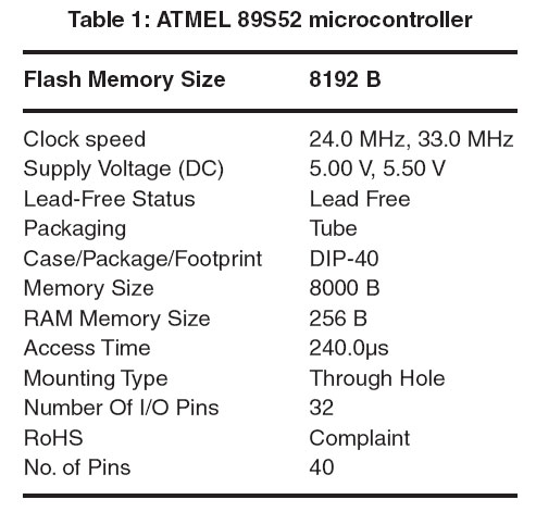
| Table 1 |
Microcontroller
The AT89S52 is a low-power, high-performance CMOS 8-bit microcontroller with 8Kbytes of in-system programmable Flash memory. The device is manufactured using Atmel’s high-density non-volatile memory technology and is compatible with the industry-standard 80C51 instruction set and pin out. The on-chip flash allows the program memory to be reprogrammed in-system or by a conservative non-volatile memory programmer. The AT89S52 provides the following standard features: 8K bytes of Flash, 256 bytes of RAM, 32 I/O lines, Watchdog timer, two data pointers, three 16-bit timer/counters, a six-vector two-level interrupt architecture, a full duplex serial port, on-chip oscillator, and clock circuitry.
Conclusion
This paper is suitably fulfilled the basic things such as avoidance of accidents inside the gate and the avoidable of a gatekeeper. It avoids the railway accidents and provides safety. We have seen little improvement in railway accidents. We also observed stronger safety records in certain areas and believe they are the result of constant efforts to improve safety. We demonstrate that it is possible to improve the overall safety of the railway system in India. We believe that success depends on both the railway industry and the regulator working together to achieve that common goal. The proposed system provide the means for real time inspection, review and data collection for the purpose of maintenance on the movable and fixed facilities for the guarantee of operation safety and maintenance efficiency as well as the safety appraisal decision-making system based on the share of safety data.
Acknowledgement
We are very thankful to Mr. Vishal Bharti, Head of Department of Computer Science and Engineering who gives us the opportunity to make the research paper and also our research mentor Prof. Sarita, Associate professor of Computer Science And Engineering who has guided us in every step in completing this research paper and also thanking to our project mentor Prof. Neha Malik, Assistant professor of Computer Science And Engineering who has guided in completing our project since now. We are in last phase of our project and till from starting she is helping us to clear out every hurdle.
References
- A complete reference of Micro Controllers, “Natwar Singh”.
- Railways overview- a technical magazine.
- The 8051 microcontroller and embedded systems “Muhammad Ali Mazidi”
- 8051 Microcontroller: An Applications Based Introduction by “David Calcutt, Frederick Cowan, and Hassan Parchizadeh”
- C and the 8051 by Tom Schultz.
- Der Keil C51-Compiler by “Michael Baldischweiler”
- San Francisco s “Advanced automatic warning signal system” in Proc. CERIE 2010, paper C, p. 297, 2010
Automatic Railway Gate Control System
August 26, 2018Sanchit Jain
Build 6 real life Projects in just one course; Inclusive of Pre-bundled IoT Kit. Rated 4.2+ by 3500+ people. Enroll Now!
Mishaps at level crossings are the biggest killer in Indian railways. Accounting for 40% of train accidents and 66% of fatalities. India has more than 30,000 level-crossings at which vehicles can cross the railway tracks. Of these, more than 11,000 are unmanned crossings. This is where most of the accidents occur. Railway gate accidents are not unique to India. On average, each year around 400 people in the European union and over 300 in the United States are killed in level crossing accidents. Collisions can occur with vehicles as well as pedestrians. Pedestrian collisions are more likely to result in a fatality.
Automatic railway gate control systems have proved to be most suitable solution to such instances. Helping in automatically opening and closing the railway gate upon detecting arrival or departure of the train. This article aims to familiarize you with advantages of automatic railway gate control systems, their implementation in the real world and help you build your own project model.
Advantages
- Automatic railway gate control systems reduce the time for which gate remains closed.
- This type of gates can be employed in an unmanned level crossing where the chances of accidents is higher and reliable operation is required.
- Automatic operation prevents errors due to manual operation.
- Lastly, no human resource is required. This makes its running cost very low compared to manned gates.
Limitations
- To establish the entire network is quite costly task.
- Energy requirements are high.
- Involves complex network of connections and require skilled workforce to build it in a good manner
Real world implementation
The gates are required to be fully lowered 15 to 20 seconds before the train arrives and rise once the end of the train clears the island circuit. The time interval is controlled by a grade crossing predictor. It is an electronic device which is connected to the rails of a railroad track and activates the crossing’s warning devices (lights, bells, gates, etc.) at a consistent interval prior to the arrival of a train at a grade crossing.
Working
All grade crossing predictors rely on the changes in the electrical characteristics of the rails that occur as a train approaches the point at which the predictor is connected to the rails. As the train approaches the feedpoint, the area enclosed by inductor diminishes. Thus reducing the inductance. For measuring the inductance, a constant-current alternating current source is connected to the rails. Now the resulting voltage is measured and by ohms law the voltage measured will be proportional to the impedance. The absolute magnitude of this voltage and its rate of change can then be used to compute the amount of time remaining before the train arrives at the crossing.
As soon as the computed time for train to reach the crossing reaches to programmed threshold value, the crossing’s warning devices are activated. The earliest grade crossing predictors used analog computers to perform this calculation. But modern equipment uses digital microprocessors.
Automatic railway gate using microcontroller
This project is an attempt to build a model of automatic railway gate using simple components such as microcontrolers, reflective type IR sensor, motor driver IC and a motor. It is based on the working of IR sensors (how do IR sensors work?). As in reflective type IR sensors no IR rays are detected by the receiver when there is no object(obstruction). Whereas when a object is present rays transmitted from IR transmitter are reflected back on IR receiver and hence detected.
Two reflective IR sensors are used for sensing the arrival or departure of train. They are placed at left and right side of the railway gate. Distance between the sensors depends on the length of the train. When the train arrives, sensors on the arriving side detects it and sends this information to the microcontroler. Microcntroler controls the motors and instructs them to close the gate. During the departure, sensors on the other side detects the train, followed by running of motors to open the gate.
Automatic railway gate operation using an Android device
This project is designed to control railway gate through an android application by the station master remotely. A smartphone or tablet with with an android-OS with a graphical user interface, based on touch screen operation is used to send the instructions to open and close the railway gate. Microcontroller once again acts as the brain of the project (learn arduino with us ). A wireless connection is established between the railway gate system(microcontroler) and remote(smartphone or tablet) using Bluetooth. Further, microcontroller controls the motors and is programmed to open and close the gates when the instructions are received. Gate can be remotely controlled by station master or driver himself. Android application used can be created according to the specific needs and can have features such as sending an acknowledgment about the status of the gate to the sender.
Indian railway is considered as the life line of the nation and carries 23 million passengers daily. It is also acknowledged as fourth largest railway network in the world by size. But recently it has been in news for all the wrong reasons such as increase in number of accidents. Its the need of the hour to modernize this system to make it more safe, swift and comfortable. Automating railway gates will be the significant step forward. This articles present the already available technology which can be put to work. Provided projects provides the fundamental concepts and principles of this system which can be further used to create new designs to target the limitations of current designs such as cost and energy needs.
Enhance your technical skills with us and build the projects of future. At Eckovation you learn about the technologies which build the modern India.
Automatic Railway Gate Control Using Arduino & IR Sensor
john February 17, 2018 12 Comments
Automatic Railway Gate Control System Using Arduino & IR Sensor
About a million people have died over the past 5 years in unmanned railway crossings all over the world. At least 1/3rd of the railway crossings are unmanned due to their remote placement and less traffic. The Automatic Railway Gate Control System using IR Sensor & Arduino focuses on systematic traffic control of railway gates that are both manned and unmanned. This project will not only make the system more reliable & precise, but also save the authorities from hiring man power to do the job. You may take it as a onetime investment.
The Automatic Railway Gate Control System Project makes use of an Arduino Nano to control the whole circuit. Two Servo motors are used to open and close the railway gates. Four IR sensors are used for sensing the arrival or departure of train. The main objective is to close the railway gates when the train approaches it, so as to block vehicles from going across the track. As soon as the train moves further away from the railway crossing, the gates must automatically open to allow vehicles to cross by.
Components Used
| Components | Specification | Quantity |
| Arduino | Nano | 1 |
| Servo Motor | G9 | `2 |
| Buzzer | 1 | |
| IR LED | 4 | |
| Photodiode | 4 | |
| LM358 | 2 | |
| Preset | 10K | 4 |
| Adapter | 12V | 1 |
| LED | Red | 4 |
| Resistors | 10K | 4 |
| Resistors | 330 Ohms | 8 |
| Toy Train | 1 |
Automatic Railway Gate Control System Using Microcontroller – Circuit
The automatic railway gate control makes use of 3 PCB’s. One is for the Arduino Nano, which works as controller of the whole project. The other two PCB’s are needed for the IR pairs. I designed all the three PCBs on EAGLE CAD software. If you want to make etched PCB, refer both the figures given below.
Automatic Railway Gate Control – PCB Design for Arduino NanoÂ
Automatic Railway Gate Control System Project – PCB Design for IR Sensor Pair
Arduino Nano PCB track
IR Sensor Pair – PCB Track
If you want to make the circuit on zero PCB or breadboard refer both the figures given below.
IR Pair using LM358 Op-Amp
Automatic Railway Gate Control – Circuit Diagram
Output of all the sensors are connected to A0, A1, A2 and A3 pins of Arduino.
The pins D9 and D10 of the Arduino are PWM pins. These pins are connected to the Servo motor. Servos are controlled by sending an electrical pulse of variable width, or pulse width modulation (PWM), through the control wire.
IR pair is made with dual Op-amp IC LM358. Â Only one IC is required for a pair. A preset is used for calibration.
IR Sensors
Two IR pairs are used in the project. If you are familiar with PCB etching you can etch the PCB, but it is not necessary to use the etched PCB, you can use two IR sensors instead of one pair that is easily available in market.
IR Connection
If you are using ready-made IR sensors please replace “<†into “>†and “>†into “<†in the code, because output of ready-made IR sensor is invert of the sensor pair used in the project.
Working
Automatic Railway Gate Control System
Four sensors are used in the project as two pairs of two sensors; these sensors are kept in the both side of level crossings gate as shown in Fig 1. All the sensors are connected to Arduino.
IR Sensors Placed Along Railway Track
When train arrives from any side, it first cross the sensor1 after that cross the sensor2, in this way Arduino close the gate by sending the signal to servomotor. When train departure from any side it first cross the sensor2 after that cross the sensors, in this way Arduino open the gate.
Servomotors are used in the gate because it is very easy to use and does not require any driver IC or circuit. Servo motor has three pins. The first pin is PWM, second is Vcc and third is GND. Servo motor receives the PWM signal from Arduino and rotates the motor at fixed angle according to duty cycle of signal.
Overview of Control System
Calibration
There are two presets in an IR pair circuit. Before calibration make sure that IR LED and photo diodes are placed in front of each other, and falling on Photodiode
Now rotate the preset, till the indicator LED does not glow. Â When some barrier is placed between LED and Photo diodes, indicator LED starts glowing. This calibration procedure has to be done for all the sensors.
Video
In the video, the speed of closing & opening of gate is slow, so it would be better if you will use the slow train. For increasing, the speed of opening and closing decrease the delay in line 71, 73, 84 and 86.
Program Code
Download Program Code
In the code two libraries “EEPROM.h†and “Servo.h†are defined. In the project, two servomotors are used so in the fourth and fifth line two servomotors are defined named myservo1 and myservo2.
Now some integers are declared, “pos†is the position integer for servo. After that, four sensors are declared named “sensor1â€, “sensor2â€, “sensor3†and “sensor4†are used to connect Arduino after it an integer is declared by name buzzer.
In the void setup section both the servo motors are attached by function “myservo1.attach (5)” in this function 5 is the pin number. Now all the four sensors are declared as input device by using function “pinMode(sensor1, INPUT)”. Buzzer is declared as Output device using function “pinMode(buzzer,OUTPUT)”. Now EEPROM.write(0,0) function is used to write EEPROM of Arduino.
In the void loop section if condition is used, When value in EEPROM address1 and address2 is become zero, system come in if loop. Now a while loop is used when train come and cross the senaor1 system come in this loop, after that an if is used when train cross the senaor2, EEPROM (0) and EEPROM(1) are updated by one. This same approach is used for sensor3 and sensor3.
Another “if†loop is used in line 48 and it become true when value of EEPROM(0) is Zero and EEPROM(1) is One. After it while loop is used and it become true when train cross the senaor2 and when train cross the senaor1, EEPROM(1) is updated by Zero and EEPROM (0) is updated by One. And this same approach is used for sensor4 and sensor3.
EEPROM(1) indicates the status of gate, when value of EEPROM (1) is One gate is opened and when EEPROM(1) is Zero gate is closed
Now in line 65 an if loop is used, it become true when value of EEPROM (1) is One now servo rotate from zero to 90 degree and gate opened. “digitalWrite†function is used to make buzzer On and OFF in line 70 and 72. After all EEPROM (0) is updated to zero. This same approach is used for closing the gate.
Automatic Railway Gate Control System Alert via SMS
- ELECTRONICS
12 COMMENTS
Automatic railway gate control system is implemented to prevent accidents of the traction system at the railway crossing levels. Nowadays many accidents take place at the railway gate crossing due to uneven crossings, even when the gate is about to close. In general, a railway gate is normally operated by a gate keeper as he receives the information about the arrival of the train.
Railway safety is the most crucial aspect of railways all over the world. This is the cheapest mode of transportation all over the world, and therefore, accidents are bound to happen due to carelessness manual operations. Therefore, an automatic railway-crossing-gate controller is used to prevent accidents at unmanned level crossings to provide much needed safety. Such efficient controllers are mostly used in remote areas that often lack the services of a station master or line man at the crossing levels.
Automatic Railway Gate Control
Automatic gate control system can be implemented using different technologies such as GSM, Bluetooth, and Android. This article describes two automatic railway gate control project topics involving Android and GSM technologies.
- Railway Level-Crossing Gate Operation Remotely by an Android Device
This project is designed to control railway level-crossing gate through an Android application by the station master. This system uses Android application device for opening and closing the level-crossing gate, remotely.
Remote operation can also be achieved by any smart phone or tablet with an Android-OS with a Graphical User Interface, based on Touch Screen Operation. This system uses a microcontroller as the heart of the project, and is programmed in such a way that any control signal from the Android phone controls the motor for operating the gate.
Railway Level-Crossing Gate Operation
A Bluetooth device is interfaced with this system to achieve remote operation. Station master or driver of a train can send a command from the Android application, and therefore, the Bluetooth on the mobile phone sends the signals to the Bluetooth device attached to a control circuit. At the receiver side, this Bluetooth device receives these signals and sends them to the microcontroller.
Therefore, based on the microcontroller’s program, it sends the signals to the motor driver to operate the motor. For the operation of the motor in both the clockwise and anti-clockwise directions, a motor driver is used. This system displays the message in response to the commands given by the Android applications, such as opening and closing of the gate, in the LCD.
Here, this microcontroller based project is developed by using an Android application, and it can be further improved with a provision of sending an acknowledgment about the status of the gate to the sender and including a buzzer for alerting the persons at the gate. In this way, either the driver of the train or the station master is able to send the open or close commands to the gate remotely, through an Android portable phone.
- Railway Level-Crossing Gate Control through GSM
X
Similar to the above project, this is also a railway level-crossing gate control system, but it is implemented by using GSM technology. In this system, the railway level crossing gate is controlled by an SMS sent by the station master or the driver to the control area.
Railway Level-Crossing Gate Control through GSM
The system has a GSM modem interfaced with a control system. When a driver or station master sends an SMS ‘open’ to the GSM modem it receives that SMS and sends it to the microcontroller. The microcontroller acknowledges these signals and sends the command signals to the motor driver IC, which controls the direction of the motor for opening and closing the gate. Therefore, this IC sends a clockwise signal to the motor to open the gate and the status gets displayed on the LCD.
In the same way, to close the gate, another SMS needs to be sent to the microcontroller. Therefore, the motor driver drives the motor in anticlockwise direction after receiving the corresponding signals from the microcontroller.
These are the two projects based on the automatic railway gate control system for the operation of gate. There are many technologies that are available to achieve this operation including Zigbee, IR, etc. Apart from this, for any help regarding any projects, you can contact us by commenting in the comment section.
Advantages. Automatic railway gate control systems reduce the time for which gate remains closed. This type of gates can be employed in an unmanned level crossing where the chances of accidents is higher and reliable operation is required.Automatic operation prevents errors due to manual operation. Automatized railway gate controller
- AUTOMATIZED RAILWAY GATE CONTROLLER Project Guide :
- Ø The aim of this project is to automatize the railway crossings in order to avoid accidents due to human negligence. Ø To control the opening or closing of gate two reference points are required to be fixed at either side of crossing. RF1 and RF2 are the two reference points at which actuation for closing and opening of gate respectively are to be initiated. When the train approaches RF1, the gate is closed and when train levels RF2, gate is opened and vice-versa.
- Ø This project utilizes two powerful IR transmitters and two receivers: one pair of transmitter and receiver is fixed at up side (from where the train comes) at a level higher than a human being in exact alignment and similarly the other pair is fixed at down side of the train direction. Ø When foreside receiver gets activated, the gate motor is turned on in one direction and the gate is closed and stays closed until the train crosses the gate and reaches aft side sensors. When aft side receiver gets activated motor turns in opposite direction and gate opens and motor stops. Ø The reference point settings depend on the following factors: 1. Minimum breaking distance. 2. Speed allowed on that particular track. 3. Road traffic density, so as to clear the traffic before actually the gate is closed.
- Ø Modulation used: ASK(Amplitude Shift Keying) Ø ASK is a form of amplitude modulation that represents digital data as variations in the amplitude of a carrier wave. Ø Also called On-Off keying. Ø Carrier frequency: 434 MHz Ø Baud Rate: 4800 bps
- Ø Microcontroller used- AT89S8253 – 8051 Ø 2.7V to 5.5V Operating Range Ø 32 Programmable bidirectional I/O Lines
- Ø The transmitter is a simple IR transmitting LED. The transmitted rays are not visible. Ø The IR receiver is an electronic component whose resistance decreases with increasing IR intensity. It is also called as “Photo diode”
- Block Diagram Circuit Diagram
- v The advantage of this system is that human error is eliminated from the picture. v The problem of accident risks at unmanned level crossings is solved. v Installation of this system will lead to accurate and precise regulation of railway crossings. v Financial burden on railways is reduced due to reduction of manpower.
- Automatic Railway Gate controller can be successfully implemented using both wired and wireless techniques. This type of designs are well suited in the field of communications. Based on this design we can transmit any information in the form of pulses. Since it is a demonstration part, the range of the transmitter is limited, the limitation being the power transmitted by the transmitter and antenna. However the range can be increased by increasing the power radiating capacity of the transmitter.

Reviews
There are no reviews yet.